

Karyakin — Boiler Installations and Steam Generators: Equipment and Processes
A thermal power plant (TPP) is an industrial facility that supplies electrical and thermal energy to its consumers. TPPs that generate only electrical energy are known as condensing power plants, while those that produce both electrical and thermal energy are referred to as combined heat and power (CHP) plants—or, in Russian terminology, *teploelektrotsentral* (TEC).
All the technological equipment at a thermal power plant is categorized into a number of distinct plant units (or facilities). Each unit comprises equipment whose operation is functionally interconnected and directed toward the production of a specific output.
Download – Karyakin — Boiler Installations and Steam Generators: Equipment and Processes >>
Along with the turbine unit and the electric generator, a key component of a thermal power plant (TPP) is the boiler installation, which produces the superheated steam required to drive the steam turbines that, in turn, rotate the electric generators.
It should be noted that boiler installations are not exclusive to thermal power plants. Many industrial facilities also utilize boiler installations to meet their own requirements for steam and hot water; these are referred to as industrial boiler installations. Additionally, there are boiler installations designed solely to supply hot water for space heating and domestic use—these are known as heating boiler installations, or simply heating boilers.
Thus, a boiler installation at a thermal power plant (hereinafter referred to as a “boiler installation”) is defined as a complex of equipment designed to generate superheated steam and supply it to steam turbines. A single thermal power plant typically houses multiple boiler installations; the exact number depends on the plant’s capacity and can reach twenty or more units.
As a technological component of a thermal power plant, a boiler installation consists of both primary and auxiliary equipment.
The primary equipment is the steam boiler. Auxiliary equipment includes fuel preparation systems, draft and forced-air systems, ash-collection systems (when solid fuel is used), and the chimney (flue stack).
A schematic diagram illustrating the layout and interaction of the equipment within a boiler installation that utilizes solid fuel is presented in Fig. 1.
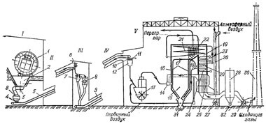
Fig. 1. Technological equipment used in steam generation at a solid-fuel thermal power plant<
I — receiving and unloading area; II and IV — conveyor galleries for the first and second stages of elevation; III — crushing area; V — boiler house building; 1 — railcar dumper; 2 — fuel hopper; 3 — fuel feeder; 4 and 10 — horizontal conveyors; 5 — first-stage elevation conveyor; 6 — electromagnet; 7 — screens; 8 — crusher; 9 — second-stage elevation conveyor; 11 — tripper (discharger); 12 — raw fuel hoppers for steam boilers; 13 — coal pulverizing mills; 14 — burners; 15 — boiler furnace; 16 — furnace lining (refractory setting); 17 — furnace waterwalls (screens); 18 and 19 — horizontal and descending gas ducts; 20 — boiler transition zone; 21 and 22 — radiant and convective superheaters; 23 — reheater; 24 — economizer; 25 — air preheater; 26 — cold air duct/plenum; 27 — forced-draft fan; 28 — ash collector; 29 — induced-draft fan; 30 — chimney (stack); 31 and 32 — ash and slag removal systems.
The operation of a boiler installation involves the movement of fuel, air, combustion products, water, and steam; the paths along which these substances travel are referred to as “circuits” or “ducts.” There are five such circuits in a boiler installation: the fuel circuit, the air circuit, the gas circuit, the water circuit, and the steam circuit. Since the gas circuit is a continuation of the air circuit, they are often combined and collectively termed the “gas-air circuit.” The combined water and steam circuit is referred to as the boiler’s water-steam circuit.
The fuel handling system of a boiler plant—the path along which fuel travels—begins at the receiving and unloading facility (I) when solid fuel is used (Fig. 1.1). This is where solid fuel, arriving at the thermal power plant by rail, is received and unloaded. The fuel is unloaded into hoppers (2) using railcar dumpers (1). From these hoppers, the fuel is moved by feeders (3) onto horizontal conveyors (4) and then transported via the first-stage inclined belt conveyors (5) to screens (7), which separate out smaller pieces that do not require crushing. Following this screening process, the larger pieces of fuel are sent to crushers (8) in the crushing section (III), where they are reduced to a size of no more than 25 mm. To prevent damage to the crushers, any metal objects present in the fuel stream are removed by electromagnetic separators (6). Additionally, wood fragments are removed from the fuel using specialized wood-removal devices (not shown in Fig. 1.1). Once crushed, the fuel is combined with the smaller fraction previously separated by the screens and transported via second-stage inclined conveyors (9) to a horizontal belt conveyor (10) located in the bunker gallery of the boiler building (V). From this belt conveyor, the crushed fuel is discharged by means of trippers (11) into the raw-fuel hoppers (12) of the individual steam boilers. This concludes the stage of preliminary preparation of solid fuel for pulverized combustion, which consists of removing metallic and woody impurities from the fuel and crushing it.
In the next stage of preparing solid fuel for pulverized combustion, the fuel is ground and dried within pulverization systems. Crushed fuel from the raw-fuel bunkers (12) is fed into coal-grinding mills (13)—the core components of the pulverization systems—where it is pulverized and dried by hot primary air supplied to the mills from the boiler air preheaters (25). The drying of the fuel dust can be carried out using either hot air or flue gases. Once prepared, the fuel dust is transported to the burners (14), marking the end of the fuel supply path in a thermal power plant. Through these burners, the fuel dust is injected into the boiler furnaces (15), where combustion takes place. To support the combustion process, hot secondary air—also drawn from the air preheaters (25)—is supplied to the boiler furnaces via the burners.
The combustion of fuel dust within the boiler furnace generates high-temperature gaseous combustion products (flue gases), as well as solid combustion residues, specifically ash and slag. Gaseous combustion products (flue gases) transfer a portion of their heat to the furnace wall tubes 17, which are positioned along the walls of the furnace. The gases then rise and exit the furnace through an opening into a horizontal gas duct 18, proceed into a downward gas duct 19, and are directed toward an ash collector 28. Once the flue gases have been cleared of fly ash in the ash collector, an induced-draft fan 29 discharges them into the atmosphere via a chimney 30. This path taken by the flue gases is known as the gas circuit of the boiler installation; it begins at the outlet of the burners located within the furnace and ends at the top of the chimney.
The air circuit of a boiler installation is designed to supply the air required for fuel combustion to the furnace, as well as to the fuel-pulverization system for the purpose of drying the fuel. Air is drawn into the circuit by forced-draft fans 27 through intake vents located in the upper section of the boiler house and is then directed to the boiler’s air preheater 25. Upon exiting the air preheater—where it has been heated to a temperature of 300–400°C—the air is divided into two streams. The first stream, known as primary air, is fed into the fuel-pulverization system to dry the fuel and subsequently transport it to the burners. The second stream (secondary air) is directed into the boiler furnace through the burners to facilitate fuel combustion. Thus, the air circuit of a boiler installation begins at the air intake vents of the forced-draft fans and ends at the burners of the boiler’s combustion chamber. Since the gas path of a boiler unit begins immediately where its air path ends, these two are combined into a single system known as the gas-air path of the boiler unit.
Within the boiler itself—a component of the boiler unit—there is what is termed the steam-water path. This path consists of an economizer section (for heating the water), an evaporating section, and a superheating section. The evaporating section is the component that determines how the medium moves through the system; based on this, steam boilers are classified into those with natural circulation and those with forced circulation.
The boiler unit shown in Fig. 1.1 features a high-pressure boiler with forced circulation. Boilers with forced circulation are also referred to as “once-through” (or straight-flow) boilers, because the water—and subsequently the steam—moves in a continuous, direct flow without passing through any intermediate vessels. In the once-through boiler shown in Fig. 1.1, the steam-water path begins at the economizer inlet headers (24), into which feedwater is supplied from the thermal power plant’s turbine unit via a feed pump.
In the economizer, the feedwater is heated and then directed through the lower headers into the furnace waterwalls. Within these waterwalls, the water from the economizer is heated to its boiling point and then flows into the boiler’s transition zone (20), where it is converted into saturated steam. This steam then enters the radiant superheater (21), where it undergoes partial superheating. Finally, the steam is heated to its target temperature in the convective superheater (22).
Download- Karyakin — Boiler Installations and Steam Generators: Equipment and Processes >>