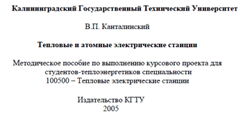
 Kantalinsky – Thermal and Nuclear Power Plants. Methodological Guide for Implementation – 2005
The Kantalinsky Methodological Manual “Thermal and Nuclear Power Plants” was reviewed and approved by the Department of Marine Power Plants and Thermal Power Engineering at Kaliningrad State Technical University.
The objectives of the course project on “Thermal and Nuclear Power Plants” are:
- systematization, consolidation, and expansion of knowledge in specialized courses;
- mastery of the principles of improving the efficiency of thermal and nuclear power plants, as well as methods for calculating the thermal flow diagrams of steam turbine units (STUs) and analyzing the impact of technical decisions made when selecting the thermal flow diagram and operating factors on the technical and economic performance of the units;
- acquisition of independent creative work skills;
- use of reference and regulatory materials, periodicals, and educational literature.
Course design for a thermal power plant should be considered as a preparatory stage of diploma design, an integral part of which, as a rule, is the selection and calculation of the thermal circuit of a thermal power plant or nuclear power plant.
-
Volume and content of the course project
The scope and content of the course project are determined by the graduating department. The following project content is recommended as a standard:
- Selecting a basic thermal diagram for a given steam turbine unit at a thermal or nuclear power plant and justifying the adopted technical solutions.
- Calculating a basic thermal diagram for a given or selected operating mode of the unit.
- Performing calculations to analyze the impact of structural changes in the thermal diagram, as well as the adopted technical solutions during its development, such as drainage discharge scheme, temperature differences in heaters, etc., on the technical and economic efficiency of the steam turbine unit.
- Determining the technical and economic performance of the unit and comparing them with standard values.
- Completing a special assignment, which may include the following:
- – improving the thermal flow diagram of the steam turbine unit, for example, by replacing surface high-pressure heaters with mixing ones;
- – changing the feedwater pump drive type;
- – changing the network water heating circuit;
- – organizing additional steam extraction, including for external heat consumers;
- – installing cogeneration banks in the condenser, etc. In this case, it is necessary to calculate the additional elements and heaters in the thermal flow diagram and determine the technical and economic efficiency of the proposed solution.
The special assignment may also include constructing energy and flow characteristics for the steam turbine unit based on multivariate calculations of the thermal diagram on a PC.
The course project includes a calculation and explanatory note (20-25 pages) summarizing the calculation results and a conclusion, as well as graphic material on one or two sheets. The first sheet depicts the basic thermal diagram of the steam turbine unit, and the second (if necessary) contains the results of the research related to the special assignment.
The note and drawings must comply with the requirements of the unified system of design and technological documentation, and the calculations must be in the SI system of units. Symbols for thermal-mechanical equipment and fittings, as well as symbols for steam, condensate, and water flows, can be adopted from [1, 2, 6].
-
Selection of a basic thermal diagram of a steam turbine plant
The basic thermal diagram of a steam turbine plant (STU) reflects the relationships between its elements and determines the process flow diagram’s efficiency and the hydroelectric power plant’s operating efficiency. When developing the basic thermal diagram, the following issues are addressed:
- The type of boilers is selected, and in the case of using drum boilers
(which is possible at subcritical steam pressure), a scheme for utilizing the heat of continuous blowdown is being developed. It is possible to use single- and two-stage continuous blowdown expanders with the exhaust steam directed to high-pressure (0.588-0.686 MPa) and atmospheric deaerators, respectively. A two-stage continuous blowdown expander scheme is used at industrial heating combined heat and power plants (with R and PT turbines), while a single-stage scheme is used at combined heat and power plants and heating combined heat and power plants. The heat of the blowdown water after the expanders is used to heat make-up water.
- The main decisions on the turbo plant regeneration scheme are substantiated, the number and type of regenerative heaters, the schemes for switching on deaerators and discharging drainage (heating steam condensate) from heaters, etc. are determined.
Mixed-flow heaters are recommended as the first low-pressure heaters (LPH) in the water flow, as they provide greater thermal efficiency.
In units with intermediate steam reheating, steam extraction for one of the high-pressure heaters (HPH) is performed from the “cold” reheat line, due to the higher efficiency of this solution compared to extracting steam from the “hot” reheat line.
The deaerator of the main water degassing stage is often included in the upstream circuit, rather than as a separate water heating stage.
When developing a thermal flow diagram, the use of superheated steam and condensate coolers in the heaters is also justified, a seal steam utilization scheme is developed, and provision is made for the installation of ejector coolers if steam-jet ejectors are used.
- The feed pump connection scheme (usually a single-lift system downstream of the high-pressure deaerator) and the feed pump drive type (electric or steam) are selected. To ensure reliable operation of the supercritical units’ feed pumps, booster pumps are installed upstream.
- A scheme for the selection of steam for fuel drying, heating of fuel oil and air (air heating is also possible with network water, condensate or feed water), as well as a scheme for switching on the turbo drive of the blowers of the boilers under pressure (in case of selecting their steam drive) is adopted.
- The method for preparing additional water (chemical and thermal), the schemes for connecting evaporators and introducing additional water into the thermal circuit of the thermal power plant are determined.
For cogeneration plants, heat is supplied to external consumers via steam and hot water, and condensate is recycled from production. Modern cogeneration turbines provide two- or three-stage (including cogeneration banks in the condenser) heating of the network water. Degassing of condensate recycled from production is carried out in atmospheric deaerators; vacuum deaerators should be used for degassing make-up water in the heating network.
Typical regeneration schemes for various turbine plants are provided in [2, 3]. They can be used as a basis for a course project…